6.2: Types of Electrical Diagrams
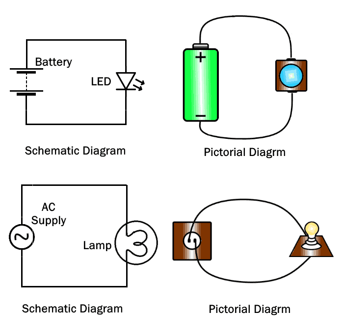
- Schematic Diagrams.
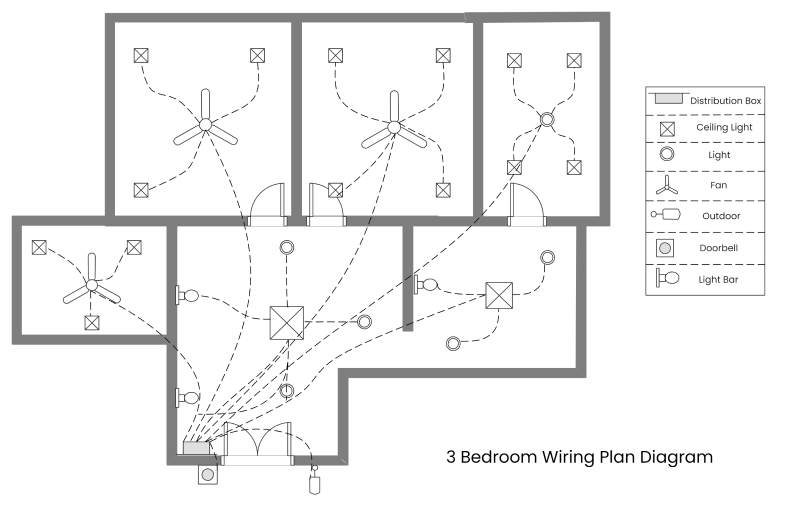
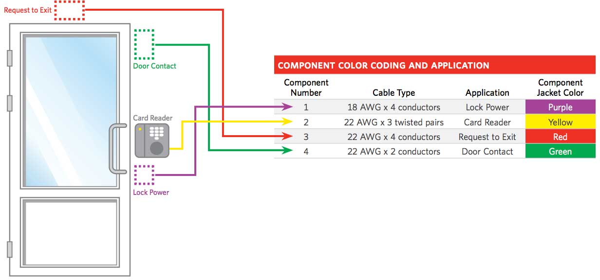
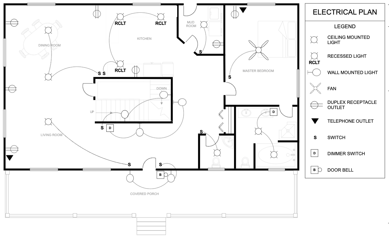
- Wiring diagrams.
- Block diagrams.
- Pictorial diagrams.
4 Basic Electrical Wiring Techniques
- Casing and Capping Wiring.
- Cleat wiring.
- Batten Wiring.
- Conduit Wiring.
There are 6 types of circuit diagrams, namely: Block Diagram, Schematic Circuit Diagram, Pictorial Circuit Diagram, Single Line Circuit Diagram, Open Circuit Diagram and Closed Circuit Diagram.

How many wiring diagrams are there : Wiring diagrams depict electrical circuits in multiple formats so electricians and engineers can visualize their projects at different levels of detail. Each of these formats provides a view of an electrical system specified for different purposes.
What are the 3 types of wiring diagrams
There are three ways to show electrical circuits. They are wiring, schematic, and pictorial diagrams. The two most commonly used are the wiring diagram and the schematic diagram. The uses of these two types of diagrams are compared in Table 1.
What is a basic wiring diagram : What is a Wiring Diagram A wiring diagram is a simple visual representation of the physical connections and physical layout of an electrical system or circuit. It shows how the electrical wires are interconnected and can also show where fixtures and components may be connected to the system.
The four-wire circuit gets its name from the fact that is uses four conductors to create two complete electrical circuits, one for each direction. The two separate circuits (channels) allow full-duplex operation with low crosstalk.
The Building Blocks of the Circuit
- Rule 1 – Electricity will always want to flow from a higher voltage to a lower voltage.
- Rule 2 – Electricity always has work that needs to be done.
- Rule 3 – Electricity always needs a path to travel.
Why use 4 wires
4-wire will give you better accuracy, especially with long wire runs. A little more if you're curious: It's all about focus. Your device wants only the sensor's resistance – not the resistance of the leadwires that connect it to the device.4-wire measurements
Two leads connect to the current source (the Force+ or High and the Force- or Low), and two connect to the voltmeter (the Sense+ or High and the Sense- or Low). The Force High and the Sense High make up one 4-wire pair and the Force Low and Sense Low make up the second 4-wire pair (see figure 4).Five rules to prevent electrical risks: Disconnect, prevent any possible feedback, verify the absence of voltage, ground and short-circuit, signal and delimit the working area.
Disconnect from the mains • Secure against reconnection • Verify that the system is dead • Carry out earthing and short circuiting • Provide protection from adjacent live parts. In the field, these are performed exclusively by electrical specialists.
What is a 4-wire system : The four-wire circuit gets its name from the fact that is uses four conductors to create two complete electrical circuits, one for each direction. The two separate circuits (channels) allow full-duplex operation with low crosstalk.
What is 4-wire protocol : In general, SPI protocol is designed with four lines to connect different devices which are SCLK (Serial Clock), SS (Slave Select), MOSI (Master Output, Slave Input), and MISO (Master Input, Slave Output) as illustrated in Figure 1. The communication in a one-slave model has only one line for slave selection. …
What does 4-wire mean in electrical
4 wire cable may refer to a cable with 4 conductors or 4 current-carrying conductors. Our 4 wire cable has four conductors: 1 white (neutral), 1 black (hot), 1 red (hot), and 1 green (equipment ground), but only three carry current for the circuit.
The three basic principles of wiring:
- Keep the length of the wire to a minimum to avoid an unnecessary voltage drop on the conductor.
- Connect wires solidly to panels and switchboards.
- Size and select the type of wires to match the current-carrying requirements of the load.
The Control4 bus may be wired using one of two topologies to install the wired or wireless keypads: star or daisy chain. Each of these topologies provides two to three ways to wire the keypads, and each topology limits the number of keypads allowed and the total bus cable length.
What is 4 core wiring : From the appearance, 4-core power cable may look like a long cable. However, when you look inside the cable, you will see multiple conductors. Single-core cable has one conductor, while multi-core cable has more than one. In the case of 4-core power cable, there are four independent conductors.


