
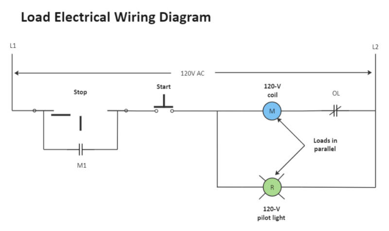
A wiring diagram shows the relative layout of the components and the wire connections between them. This type of diagram shows the physical relation of all devices in the system, the conductor terminations between these devices, and are commonly used in motor control installations.A circuit diagram is a simplified drawing of an electrical circuit. It uses a solid line to show the conductor or wires that determine the path of the circuit. On the path are symbols to represent the various parts of the circuit such as the power source and resistors.6.2: Types of Electrical Diagrams
- Schematic Diagrams.
- Wiring diagrams.
- Block diagrams.
- Pictorial diagrams.
How do you do electrical drawings : How to Draw Electrical Diagrams
- Start with a collection of electrical symbols appropriate for your diagram.
- Draw circuits represented by lines.
- Drag and drop symbols to the circuits and connect them.
- Use line hops if any lines need to cross.
How are wiring diagrams read
The electrical schematics are read from left to right or from top to bottom. This is important to get right, as the signal direction indicates the flow of current in the circuit. It is then easy for a user to understand when there is a change in the course of the circuit.
What are 3 different types of electrical wiring diagrams : Circuit diagrams represent every component and connection in a circuit for wiring installation. Schematic diagrams show how electricity flows through a circuit and use standardized symbols to map circuits. Ladder diagrams represent how a device's programming interacts with its wiring.
When drawing circuit diagrams, there are a few important rules to remember:
- Cables and wires in a circuit are drawn as straight lines.
- Wires should not cross over each other.
- We need to use the correct symbols for each component in the circuit.
- When drawn, the circuit forms a closed loop.
In this article, we will show you how to read and understand circuit diagrams for electronics repair in six steps.
- 1 Identify the Symbols. The first step is to identify the symbols used in the circuit diagram.
- 2 Follow the Flow.
- 3 Analyze the Function.
- 4 Compare the Reality.
- 5 Identify the Problem.
- 6 Document and Communicate.
What are the 2 types of schematics
Types of Electrical Diagrams or Schematics
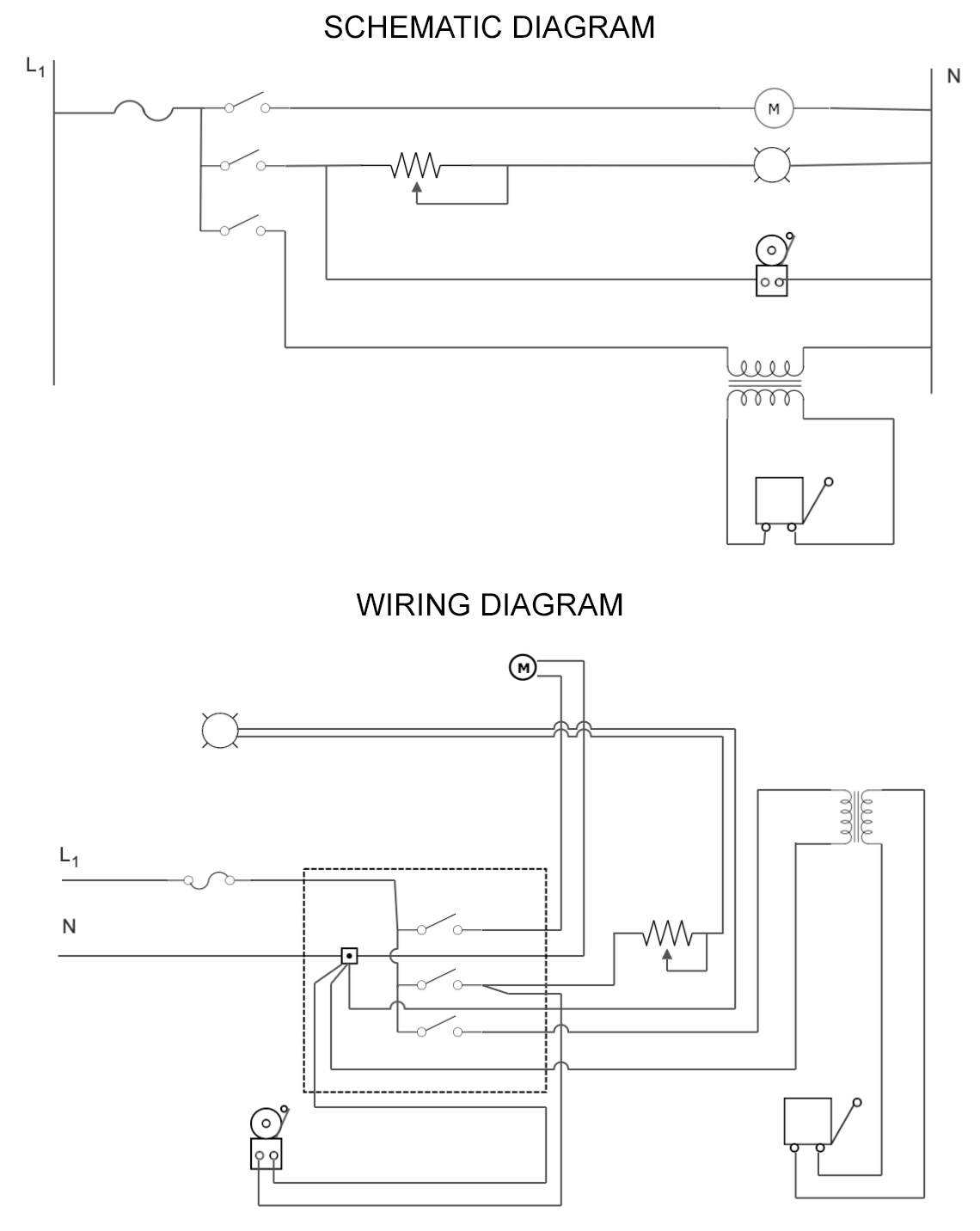
They are wiring, schematic, and pictorial diagrams. The two most commonly used are the wiring diagram and the schematic diagram.There are three ways to show electrical circuits. They are wiring, schematic, and pictorial diagrams. The two most commonly used are the wiring diagram and the schematic diagram. The uses of these two types of diagrams are compared in Table 1.Electrical drafters
Electrical drafters prepare wiring and layout diagrams used by workers who erect, install, and repair electrical equipment and wiring in communication centers, power plants, electrical distribution systems, and buildings.
In this article, we will show you how to read and understand circuit diagrams for electronics repair in six steps.
- 1 Identify the Symbols. The first step is to identify the symbols used in the circuit diagram.
- 2 Follow the Flow.
- 3 Analyze the Function.
- 4 Compare the Reality.
- 5 Identify the Problem.
- 6 Document and Communicate.
What is the difference between wiring diagram and electrical diagram : A schematic shows the plan and function for an electrical circuit, but is not concerned with the physical layout of the wires. Wiring diagrams show how the wires are connected and where they should located in the actual device, as well as the physical connections between all the components.
Why do electricians use circuit diagrams : A circuit diagram, also known as an electrical diagram, elementary diagram, or electronic schematic, is a graphical representation that simplifies an electrical circuit. It serves as a visual tool for the design, construction, and maintenance of electrical and electronic equipment.
How do I learn to design schematics
6 Steps for Creating an Electronic Design Schematic
- Create Block Diagrams to Overview Your Design.
- Label Every Net.
- Make Your Schematic as Informative as You Can.
- Identify All Pins and Connectors.
- Keep a Record of Your Electronic Design Notes.
- Use the Right Schematic Design Tools.
The electrical schematics are read from left to right or from top to bottom. This is important to get right, as the signal direction indicates the flow of current in the circuit. It is then easy for a user to understand when there is a change in the course of the circuit.A schematic shows the plan and function for an electrical circuit, but is not concerned with the physical layout of the wires. Wiring diagrams show how the wires are connected and where they should located in the actual device, as well as the physical connections between all the components.
What are the 3 basic rules for drawing a circuit diagram : When drawing circuit diagrams, there are a few important rules to remember:
- Cables and wires in a circuit are drawn as straight lines.
- Wires should not cross over each other.
- We need to use the correct symbols for each component in the circuit.
- When drawn, the circuit forms a closed loop.